


BCM-100 Cable Online Monitoring and Potential Hazard Warning & Localization System
The BCM-100 Cable Online Monitoring and Potential Hazard Warning & Localization System employs a non-contact detection method to continuously monitor partial discharge, ground loop currents, and temperature (optional) in medium- and high-voltage cables in real time.
Category:
Partial Discharge Online Monitoring System
Keywords:
Product accessories:
Email: daimirong@broadwit.com.cn
- Product Description
-
System Features and Advantages
The BCM-100 Cable Online Monitoring and Potential Hazard Warning & Localization System employs a non-contact detection method to continuously monitor partial discharge, ground loop currents, and temperature (optional) in medium- and high-voltage cables in real time.
- Real-time online monitoring
- Superior expert diagnostic system
- A robust cable fault database
- Strong anti-interference capability
- The monitoring band covers the range from 50 kHz to 100 MHz.
- Sampling rate of 100 MSa/s
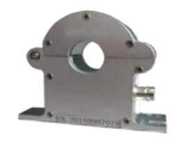
System Components – HFCT Sensor
Main technical specifications
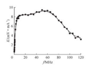
Frequency range
50kHz-100MHz
Installation method
Card-mounted
Opening inner diameter
50–100mm optional
Protection Level
IP68
Detection sensitivity
1pC
Sampling rate
100MSa/s
Signal transmission method
50Ω Coaxial Cable
The physical structure is designed in a split configuration, allowing for the detection of partial discharge pulse signals by clamping onto either the cable's ground wire or the cross-interconnected line—making on-site installation exceptionally convenient.
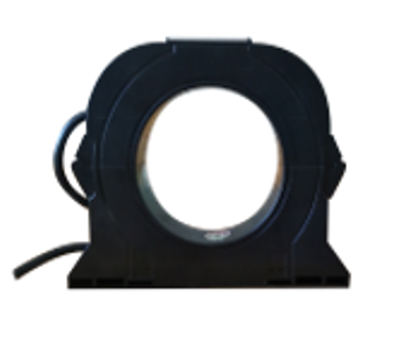
System Components – Circulation Sensor
Ground Loop Current + Synchronized Phase
Main technical specifications
Measurement range
0-100A
Measurement accuracy
±1%
Installation method
Card-mounted
Protection Level
IP68
Work environment temperature
-40°C to +65°C
Workplace humidity
95%Rh
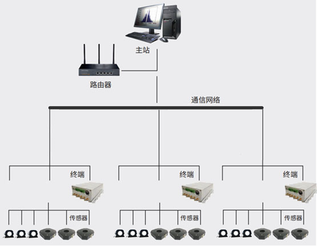
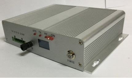
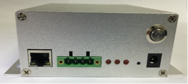
System Components – Data Acquisition Terminal
It features a modular design, comprising a power module, a communication module, and a data storage module. The power supply is localized and sourced directly from the power supply within the cable termination cabinet. The communication module handles both upstream and downstream communications: upstream, it transmits signals and data to the server; downstream, it collects data gathered by sensors. Meanwhile, the data storage module manages and stores all incoming information.
Project
Parameters
Power supply
DC 24V, 1A
Sensor interface method
BNC
Upstream communication method
RS485
Communication distance
1200 meters
Protection Level
IP55
Partial Discharge Acquisition
1) Frequency range: 50 kHz to 100 MHz
2) Built-in maximum hold circuit to prevent discharge.
Missing collection numberCirculation Data Collection
1) Frequency range: 50 Hz
2) Current range: 0–100 ATime synchronization
Built-in power frequency synchronization: 50Hz
Dimensions
236 x 235 x 65 mm
Ambient temperature
-25°C to 55°C
Environmental humidity
95%
System Architecture – Substation
The substation equipment uses an embedded operating system to collect terminal data, which is then transmitted over the network to the platform. It features three core functions: data collection, transmission, and storage.
Project
Parameters
Power supply
Adapter input: AC 220V ~ 12V DC ~ 2A
Upstream communication method
TCP/IP
Storage
16GB TF Card
Protection Level
IP55
Ambient temperature
-25°C to 55°C
Environmental humidity
95%
System Architecture – Cloud Platform
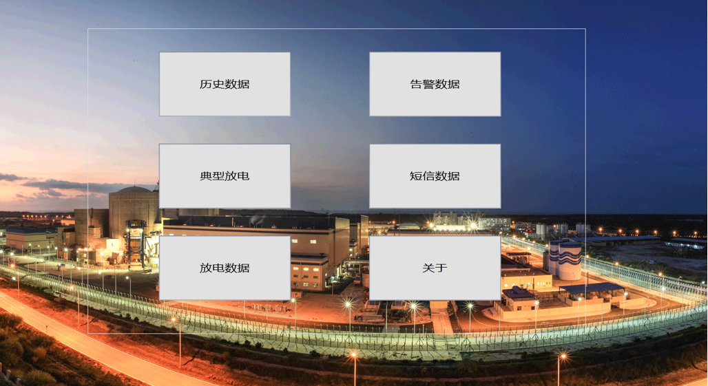
System Features – Real-Time Monitoring + Early Warning
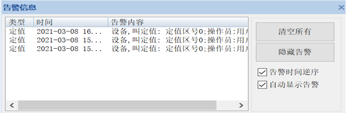
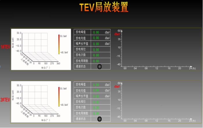
Gray: Indicates a sensor connection issue or that the sampled value is too low.
Green: indicates the sensor is functioning properly;
Yellow: Indicates that the discharge peak at the sensor's location has exceeded the warning threshold, and this area should be monitored closely.
Orange: Indicates that the discharge peak at the sensor's location is relatively high, exceeding the over-limit threshold in the set values. Strengthen inspection efforts and increase attention to this specific area.
Red: Indicates that the discharge peak at the sensor's location is very high—already exceeding the over-alert threshold. Strengthen inspections at this location and increase monitoring attention.
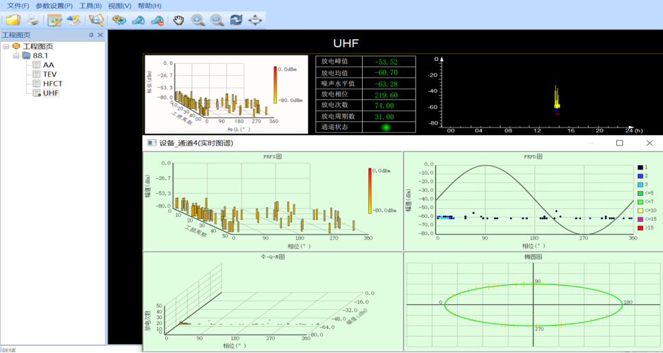
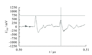
System Function – Discharge Spectrum
Discharge Distribution: φ-q Two-Dimensional Spectrogram, along with PRPS and φ-q-n Three-Dimensional Spectrograms, and Elliptical Plots
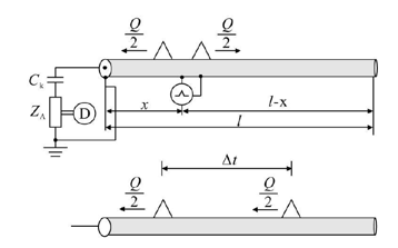
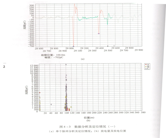
System Function – Fault Localization
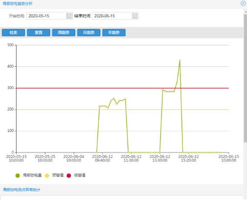
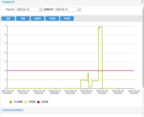
System Function – Trend Analysis
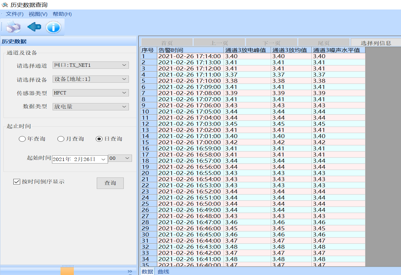
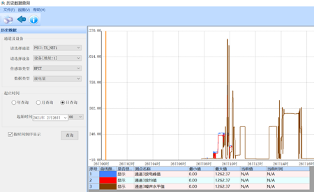
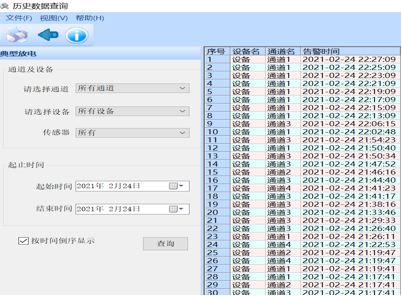
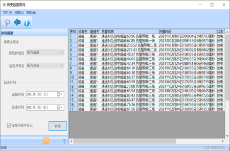
System Function – Historical Query
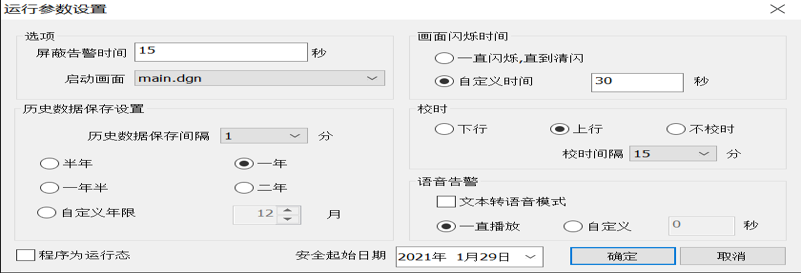
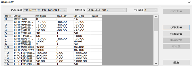
System Function – Parameter Settings
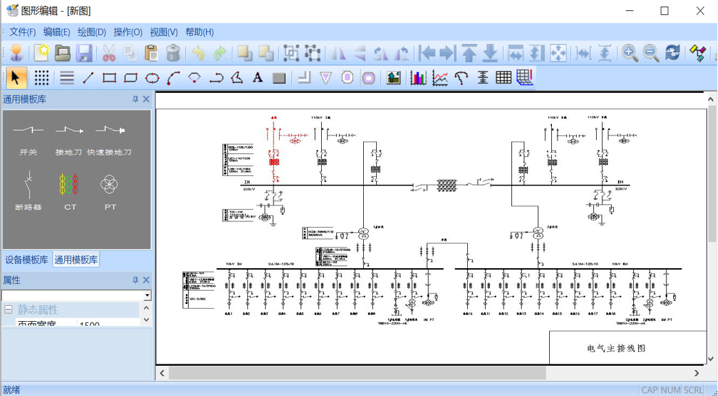
System Function – Generate System Diagram
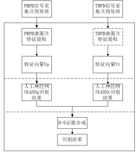
System Function – Expert Diagnostic System with Automatic Analysis Report Generation
Leave a message for inquiry
If you're interested in our products, please leave your email, and we'll get back to you as soon as possible. Thank you!
More products